Antenna Factors That Drive Smart Grid Communications
In Part I of this series we learned that Wireless Connectivity is a cost effective solutions for providing two-way controls and optimum smart grid communications. Antennas provide the critical link in that network and this white paper series will provide network designers with the tools needed to select the appropriate antenna styles for optimum smart grid communications.
Five factors were identified: Transmission RF Power, Antenna gain on transmitter and receiver, Frequency band, Receive Power Sensitivity and Path Loss. This section will cover the impact of Transmission RF Power.
Part II: Transmission RF Power
A key contributor to overall range performance of smart grid communications systems is the transmitter radio frequency (RF) power as it applies to the antenna input. The higher the transmitter RF power going into the antenna the further the range will be increase. But there are limits to what is allowed. In the US, the Federal Communication Commission (FCC) set restrictions on the Effective Isotropic Radiated Power (EIRP) allowed on all frequencies for all wireless devices. If the wireless device is cellular, then additional PCTRB certification is required in order to be in compliance with many of the Cellular Carriers Networks (for example, AT&T, Verizon, T-Mobile, and US Cellular).
Effective Isotropic Radiated Power (EIRP) is determined by a combination of both the actual radio frequency power transmitted by the radio, as measured in watts or dBm, and the antenna gain at a typical 3m distant away.
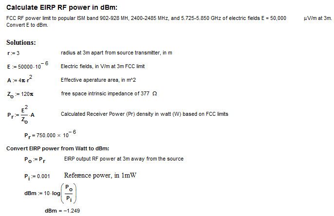
If wireless systems operate within popular ISM unlicensed bands and utilized analog modulation and fixed radio frequency carrier, then the FCC under part 15 restricts RF power limit to 50,000 µV/m at 3m or EIRP power of -1.25 dBm at 3m. This EIRP RF power limit of -1.25 dBm at 3m is ideal for short range applications. A sample calculation with formulas below illustrates how to calculate and convert FCC EIRP limits from electric fields in µV/m at 3m to absolute RF power in dBm:

If wireless systems operate within popular ISM unlicensed bands and the transmitters utilized spread spectrum technology then FCC EIRP restrictions under part 15 allow the transmission point to go up to 36dBm. The two main spread spectrum types are frequency hopping, FHSS and digital modulation scheme, DSSS. These wireless transmitters are permit to transmit a maximum of 1 watt (or 30 dBm) into the 6dBi gain Omni-directional or Directional antenna. However, this requirement is less restrictive if 2.4 GHz and 5.8 GHz wireless device are use for point-to-point applications.
The popular unlicensed ISM bands are:
• 902-928 MHz
• 2.400-2.4835 MHz
• 5.725-5.850 MHz
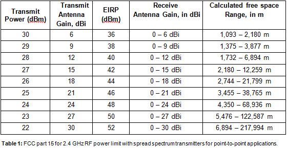
For 2.4 GHz band, the FCC allows the EIRP to be increased above 36 dBm but certain restrictions apply. The antenna must be directional and for every 3dBi antenna gain increase, the RF transmit power applying into the antenna must be reduce by 1 dBm. The table 1 below shows combination of allowed transmit power / antenna gain and the resulting EIRP and range coverage up to 218 km for wireless point-to-point applications in free space. The range is the total distant between a transmitter and a receiver in meters. This range calculation is relatively lower compared to Friss formula since it includes a 20dB for wireless operating signal margin.

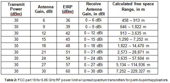
The 5.8 GHz band used exclusively for fixed, point-to-point operations may employ transmitting antennas with directional gain greater than 6 dBi without any corresponding reduction in 1 Watt (or +30 dBm) conducted transmitter output power limit. Table 2 below shows combinations of allowed transmit power / antenna gain and the resulting EIRP and range opportunity up to 229 km in free space. The range is the total distant between a transmitter and a receiver measured in meters. This range calculation is relatively low compared to Friss formula since it includes a 20dB for wireless operating signal margin.

The theoretical example given above ignores the impact of beamwidth. Increasing the RF power allows the radiation pattern to stay the same, whereas increasing the gain of the antenna results in a narrower beam-width. A narrower beamwidth may make it harder to align the transmitting antenna with the receiving antenna, especially at long distances due to the earth curvature.
The responsibility for staying within FCC approved power limits falls on the operator or professional installer.
Many parameters are involved in a standard smart grid communications wireless system. Consequently, we will examine the system’s ability to digitally communicate over a wide distant in dynamic environments in a best-case scenario.
This section, Part II, has addressed the guidelines associated with Transmission RF Power, the effects of antenna gain on transmitter and receiver will be examined in detail in Part III of this series.
About Mobile Mark, Inc.:
Mobile Mark, Inc. is a leading global supplier of antennas to wireless companies. Many of our products feature innovative, patented designs, available only from Mobile Mark. The company was established in 1984 and currently has two locations: global headquarters near Chicago, IL and our factory near Birmingham, England. We offer an extensive line of antennas, including portable, fixed site, and mobile. In addition, we offer custom design products for specialized OEM applications.
Antennas made by Mobile Mark Inc. are already in use on commercial and residential smart metering, distribution utility poles, and utility company. Mobile Mark’s experience has given the company an appreciation for some of the wireless challenges these new networks are facing in their efforts to provide effective smart grid communications. To learn more about our antenna design for smart grid communications and other products and services, contact Mobile Mark at info@www.mobilemark.com, 1-800-648-2400 or 847-671-6690.
